LED Bulb Setup

Getting Started

step-1.png

Turn off your lamp or light fixture and install LED Bulb.

step-2.png

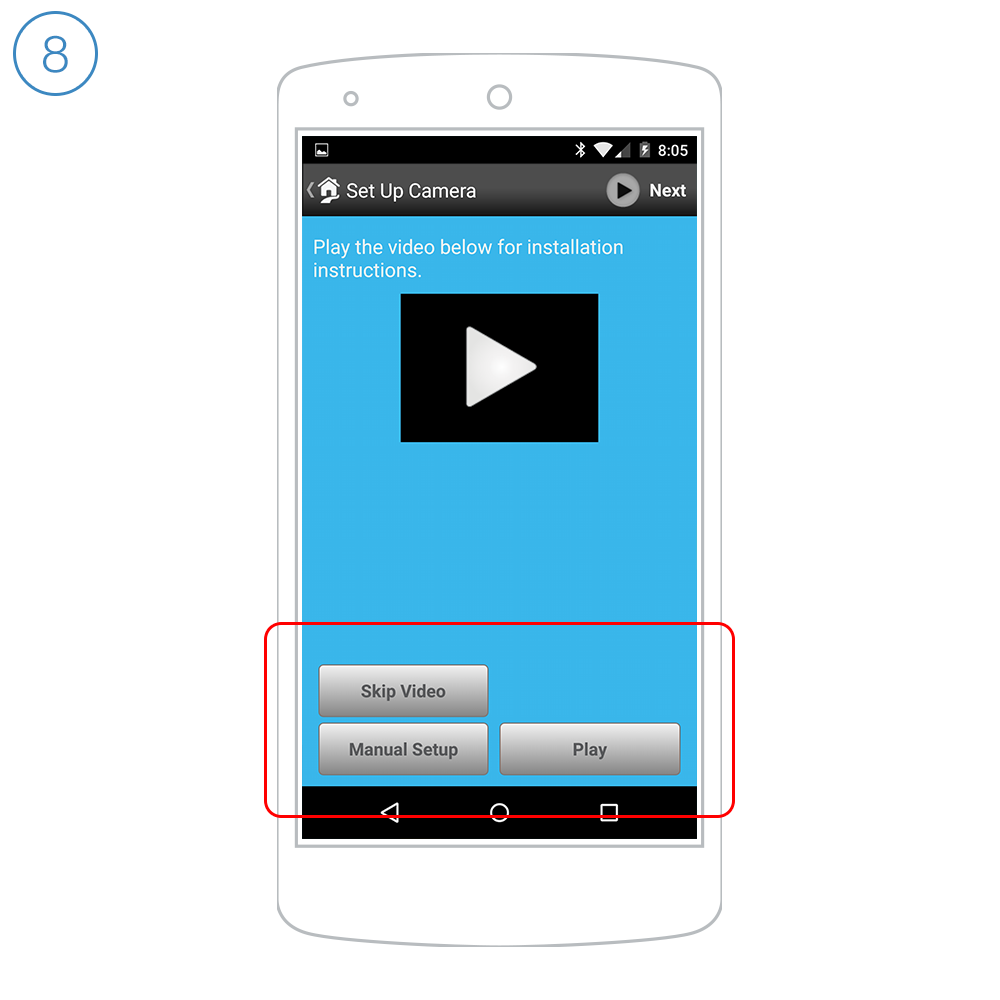
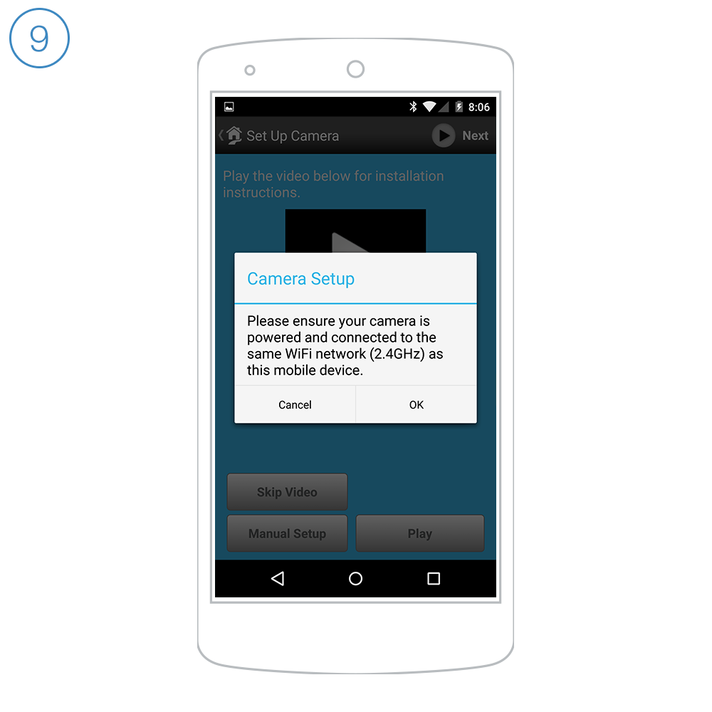
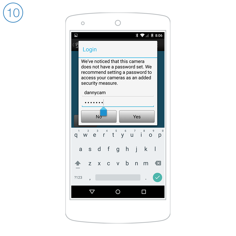
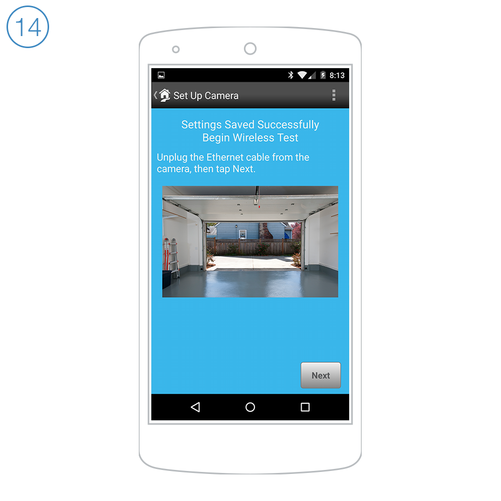
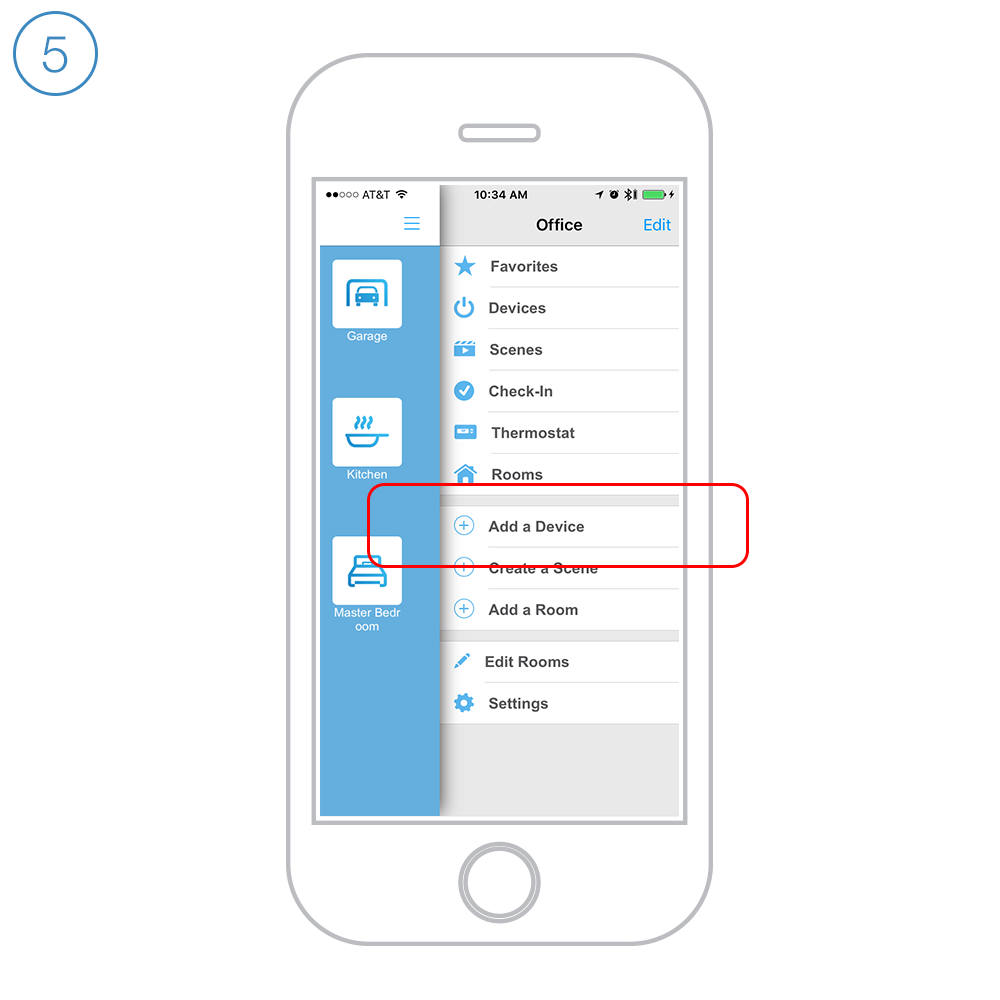
Follow the on-screen instructions in the Insteon app to add LED Bulb.

The Insteon app requires Insteon Hub.
Learn More →

step-3.png

When prompted, turn on your lamp or light fixture.

 
dont-dim.png

Do not connect LED bulb to dimmers. Instead, link LED Bulb with Insteon remotes and switches to dim.

turn-off.png

After installation, leave your lamp on. If you turn off your lamp, you won't be able to control LED Bulb.

no-power.png

After a power outage, LED Bulb will turn on.


Guides and Manuals

Quick Start Guide

Owner's Manual


Going Further


Outdoor On/Off Module Setup

Guides and Manuals

Quick Start Guide

Owner's Manual


Going Further

HomeKit-enabled Bridge Setup

Guides, Manuals and Downloads

Quick Start Guide

Owner's Manual

Downloads

Use the Apple Home app that comes pre-installed on your iOS device


Basic Troubleshooting

Get Started with Starter Kits


All Starter Kits


On/Off Module Setup

Getting Started

step-1.png

Turn on your lamp or appliance and connect its power cord to On/Off Module.

step-2.png

Plug On/Off Module into a power outlet.

step-3.png

Follow the on-screen instructions in the Insteon app to add On/Off Module.

 
step-4.png

When prompted, press and hold the set button until On/Off Module beeps.


Guides and Manuals

Quick Start Guide

Owner's Manual


Going Further


Dimmer Module Setup

Getting Started

step-1.png

Turn on your lamp and connect its power cord to Dimmer Module.

step-2.png

Plug Dimmer Module into a power outlet.

step-3.png

Follow the on-screen instructions in the Insteon app to add Dimmer Module. The Insteon app requires Insteon Hub.

 
step-4.png

When prompted, press and hold the set button until Dimmer Module beeps.


Bulb Compatibility

 
bulb-types.png

Only use dimmable bulbs with Insteon Dimmer Module


Guides and Manuals

Quick Start Guide

Owner's Manual


Going Further


Dimmer Outlet Setup

Getting Started

step-1.png
Turn off power at the service panel and remove the existing wall outlet.
step-2.png

Connect the corresponding wires from the junction box to the Insteon Wall Outlet and cap them with wire nuts.

if your outlet's wires do not match the diagram, consult the additional wiring diagrams available below.

step-3.png
Install the Insteon Wall Outlet, attach the wall plate and turn on power.
 
step-4.png

Follow the on-screen instructions in the Insteon app to add Dimmer Outlet.

step-5.png

When prompted, press and hold Dimmer Outlet's set button until you hear a double beep.

Dimmer Outlet requires that the Outlet Dimmer Key be fitted to any plug connected to the top, dimmable outlet.


Bulb Compatibility

 
bulb-types.png

Only connect lamps with dimmable bulbs to Dimmer Outlet's upper outlet.


Guides and Manuals

Quick Start Guides

Owner's Manuals


Wiring Diagrams

End of Run Outlet


Connect the Line, Neutral and Ground wires.

end of run.png

Middle of Run Outlet

Connect the Line, Neutral and Ground wires. If your old outlet connected to ground with a pigtail, you can discard it.

middle of run.png

Switched Outlet

Connect the Line, Neutral and Ground wires. Disconnect and cap the switched wire (usually red).

In this configuration, the wall switch that controls this outlet will no longer function. If you would like to preserve control of your outlet from the wall switch, replace the switch with Insteon Wall Switch.

switched outlet outlet.png

In the junction box that houses the wall switch, replace the standard switch with an Insteon Wall Switch. Connect the Line, Neutral and Ground wires. Cap the switched wire (usually red). Cap the red load wire on the Insteon Switch.

After wiring is complete, link the Insteon Wall Outlet and Wall Switch together.

  1. Turn on both the Insteon Outlet and the Insteon Wall Switch. On Insteon Wall Switch, press and hold the set button until Wall Switch beeps.

  2. On Insteon Wall Outlet, press and hold the set button until Wall Outlet double-beeps.

  3. On Insteon Wall Outlet, press and hold the set button again until Wall Outlet beeps.

  4. On Insteon Wall Switch, press and hold the set button until Wall Switch double-beeps.

switched outlet switch.png
 

Basic Troubleshooting


On/Off Outlet Setup

Getting Started

step-1.png
Turn off power at the service panel and remove the existing wall outlet.
step-2.png

Connect the corresponding wires from the junction box to the Insteon Wall Outlet and cap them with wire nuts.

If your outlet's wires do not match the diagram, consult the additional wiring diagrams available below.

step-3.png
Install the Insteon Wall Outlet, attach the wall plate and turn on power.
 
step-4.png

Follow the on-screen instructions in the Insteon app to add On/Off Outlet.

step-5.png

When prompted, press and hold On/Off Outlet's set button until you hear a double beep.


Guides and Manuals

Quick Start Guides

Owner's Manuals


Wiring Diagrams

End of Run Outlet

Connect the Line, Neutral and Ground wires.

Middle of Run Outlet

Connect the Line, Neutral and Ground wires. If your old outlet connected to ground with a pigtail, you can discard it.

Switched Outlet

Connect the Line, Neutral and Ground wires. Disconnect and cap the switched wire (usually red).

In this configuration, the wall switch that controls this outlet will no longer function. If you would like to preserve control of your outlet from the wall switch, replace the switch with Insteon Wall Switch.

switched outlet outlet.png

In the junction box that houses the wall switch, replace the standard switch with an Insteon Wall Switch. Connect the Line, Neutral and Ground wires. Cap the switched wire (usually red). Cap the red load wire on the Insteon Switch.

After wiring is complete, link the Insteon Wall Outlet and Wall Switch together.

  1. Turn on both the Insteon Outlet and the Insteon Wall Switch. On Insteon Wall Switch, press and hold the set button until Wall Switch beeps.

  2. On Insteon Wall Outlet, press and hold the set button for the outlet that you would like to control until Wall Outlet double-beeps.

  3. On Insteon Wall Outlet, press and hold the same set button until Wall Outlet beeps.

  4. On Insteon Wall Switch, press and hold the set button until Wall Switch double-beeps.


Basic Troubleshooting


Wi-Fi Camera Setup on Android

Getting Started

step-1.png

Connect your camera to power and your router. You won't need ethernet after setup.

step-2.png

Connect the cables to your camera.

step-3.png

Launch the Insteon app on your Android device.

Setup with iPhone, iPad, iPod touch or Android devices requires Insteon Hub and the Insteon app.

 
step-4.png

Navigate to Settings by tapping Edit Settings from the Settings button

step-5.png

Tap Devices

step-6.png

Tap the Add button

 
step-7.png

Tap Camera

step-8.png

Tap Play to watch the setup video or tap Skip Video to continue with setup

step-9.png

If you have not already done so, connect your camera to power and your router using the supplied cables. It can take up to two minutes for your camera to complete its startup process. When ready, tap OK.

 
step-10.png

Give your camera a user name and password. This information is used to secure your camera and should be different from your Insteon account.

  • The maximum password length is 12 characters

  • The password must contain letters and numbers only, no special characters (!@#$%^&*, etc.) are permitted

  • The password cannot contain spaces

When ready, tap Yes.


Connecting with Wi-Fi

Follow these steps if you want to connect your camera using Wi-Fi

Connect using ethernet instead →

step-11.png

Choose the Wi-Fi option that applies to your network: password-protected or open.

step-12.png

Enter your Wi-Fi network password and tap Done.

step-13.png

Wait while your camera's settings are updated

 
step-14.png
When prompted, disconnect the ethernet cable from your camera and tap Next.

If you do not disconnect the ethernet cable, your camera will not switch to Wi-Fi.

step-15.png

Wait while your camera reconnects to Wi-Fi

step-16.png

Name your camera, select an icon and add it to a room.

 
step-17.png

Scroll down and write down the Local IP Address and IP Port. When ready, tap Done.

step-18.png

Return to Settings by tapping Edit Settings from the Settings button

step-19.png

Tap House

 
step-20.png

Write down the Gateway IP address and Subnet Mask. You should now have the following information:

  • Camera IP Address

  • Camera Port

  • Gateway IP Address

  • Subnet Mask

Dismiss settings and follow the steps in this article to complete port forwarding and manual remote access setup.


Connecting with Ethernet

Follow these steps if you want to connect your camera using Ethernet

step-11e.png

Tap Use hardwired with an Ethernet cable

step-12e.png

Wait while your camera's settings are updated

step-13e.png

Name your camera, select an icon and add it to a room.

 
step-14e.png

Scroll down and write down the Local IP Address and IP Port. When ready, tap Done.

step-15e.png

Return to Settings by tapping Edit Settings from the Settings button

step-16e.png

Tap House

 
step-17e.png

Write down the Gateway IP address and Subnet Mask. You should now have the following information:

  • Camera IP Address

  • Camera Port

  • Gateway IP Address

  • Subnet Mask

Dismiss settings and follow the steps in this article to complete port forwarding and manual remote access setup.


Guides, Manuals and Downloads

Quick Start Guide

Owner's Manual

Downloads


Basic Troubleshooting


Optional Wall Mount


Mount the optional bracket using screws and wall anchors.

Different wall materials require different fasteners. Use the appropriate type for your mounting surface. Drywall screws and anchors have been provided. Use caution when drilling holes in walls that may contain live electrical wires.


Camera Firmware


Current Wi-Fi Camera Firmware

Device 11.37.2.59
Web UI 2.001.10.9


Wi-Fi Camera Setup on iPhone, iPad and iPod touch

As of December 31 2016 Insteon will no longer provide technical support for standard definition cameras (75790/75790WH)

Getting Started

step-1.png

Connect your camera to power and your router. You won't need ethernet after setup.

step-2.png

Connect the cables to your camera.

step-3.png

Launch the Insteon app on your iPhone, iPad or iPod touch.

Setup with iPhone, iPad, iPod touch or Android devices requires Insteon Hub and the Insteon app.

 
step-4.png

Tap the drawer icon or swipe from the right edge of the display to open the drawer.

step-5.png

Tap Add a Device.

step-6.png

Tap Camera.

 
step-7.png

If you have not already done so, connect your camera to power and your router using the supplied cables. If can take up to two minutes for your camera to complete its startup process. When ready, tap Next.

step-8.png

Select the camera that you
would like to configure.

step-9.png

Give your camera a user name and password. This information is used to secure your camera and should be different from your Insteon account.

  • The maximum password length is 12 characters

  • The passvword must contain letters and numbers only; no special characters (!@#$%^&*, etc.) are permitted

  • The password cannot contain spaces

When ready, tap Next. If the Next button is disabled, your password does not meet the password restrictions.


Connecting with Wi-Fi

Follow these steps if you want to connect your camera using Wi-Fi

Connect using ethernet instead →

step-10.png

Tap use Wi-Fi and select your network from the list. If you don't see your network, ensure that you've connected the antenna to your camera.

step-11.png

Enter your Wi-Fi network password and tap Next.

step-12.png
Disconnect the ethernet cable from your camera and restart the camera by disconnecting and then reconnecting your camera's power cable.

If you do not disconnect the ethernet cable, your camera will not switch to Wi-Fi.

 
step-13.png

To see your camera when you are away from home, you will need to configure remote access.

Write down the IP Address displayed at the bottom of the screen and tap Next.

step-14.png

Name your camera, select an icon
and add it to a room.

step-15.png

Scroll down and tap Port

 
step-16.png

Change the port from 80 to 25106.

If you are setting up more than one camera, increase the port number for each successive camera to ensure that every camera has a unique port number.

When ready, tap Done.

step-17.png

Return to Settings by dismissing
Edit Camera and Add Device.

Tap House

step-18.png

Write down the Gateway IP address and Subnet Mask. You should now have the following information:

  • Camera IP Address

  • Camera Port

  • Gateway IP Address

  • Subnet Mask

Dismiss Settings and follow these steps to assign your camera a static IP address.


Connect using Ethernet

Follow these steps if you want to connect your camera using Wired Ethernet

step-10e.png

Select Use Wired Ethernet and then tap Next

step-11e.png

Wait while your camera's settings are updated

step-12e.png

To see your camera when you are away from home, you will need to configure remote access.

Write down the IP Address displayed at the bottom of the screen and tap Next.

 
step-13e.png

Name your camera, select an icon
and add it to a room.

step-14e.png

Scroll down and tap Port

step-15e.png

Change the port from 80 to 25106. 

If you are setting up more than one camera, increase the port number for each successive camera to ensure that every camera has a unique port number.

When ready, tap Done.

 
step-16e.png

Return to Settings by dismissing
Edit Camera and Add Device.

Tap House

step-17e.png

Write down the Gateway IP address and Subnet Mask. You should now have the following information:

  • Camera IP Address

  • Camera Port

  • Gateway IP Address

  • Subnet Mask

Dismiss Settings and follow these steps to assign your camera a static IP address.


Assign a Static IP Address

Download and launch the Camera Setup Assistant for your Mac or PC.

Right-click (or control-click on a Mac) and select Network Configuration

Uncheck Obtain IP from DHCP Server. IP Address, Subnet Mask, Gateway and DNS Server should auto-populate.

If the fields are empty, enter the information gathered throughout this article their respectively fields. Use the Gateway IP Address for Gateway and DNS Server addresses.


Enter your camera password and click OK. It may take up to two minutes for your camera to restart.

static-step-5.png

Your camera is now ready for remote access setup. Follow the steps in this article to complete remote access setup on your router.


Guides, Manuals and Downloads

Quick Start Guide

Owner's Manual

Downloads


Basic Troubleshooting


Optional Wall Mount

 
step-4-optional.png
 

Mount the optional bracket using screws and wall anchors.

Different wall materials require different fasteners. Use the appropriate type for your mounting surface. Drywall screws and anchors have been provided. Use caution when drilling holes in walls that may contain live electrical wires.


Camera Firmware

 
sd-indoor-cameras.png

Current Wi-Fi Camera Firmware

Device 11.37.2.59
Web UI 2.001.10.9


Wi-Fi Camera Setup


As of December 31 2016 Insteon customer service will no longer provide technical support for the 75740 series (standard definition) cameras.

Requires an already configured Insteon Hub
 

Motion Sensor Setup

Need help setting up the new motion sensor? If so Click here

Getting Started

step-1.png

Open Motion Sensor by removing the battery cover.

step-2.png

Install the included 9V battery.

step-3.png

Follow the on-screen instructions in the Insteon app to add Motion Sensor.

 
step-4.png

When prompted, press and hold the set button inside the battery compartment.

step-5.png

Affix the sensor mount to a wall using the provided screws.

step-6.png

Replace the battery cover and slide Motion Sensor onto the mount.


Guides and Manuals

Quick Start Guides

Owner's Manuals