Locate your device's Insteon ID
All Insteon devices except for WiFi Cameras have an Insteon ID. Use this article to help locate the Insteon ID for your product.
The Insteon ID is usually printed on a small, white rectangular sticker affixed in the locations described below. All Insteon IDs take the form of three hexadecimal pairs (A1.B2.C3).
| Device | Insteon ID Location |
|---|---|
| Dimmer Module | On the back |
| On/Off Module | |
| Outdoor On/Off Module | |
| LED Bulb | On the top of the bulb lens |
| LED Bulb for Recessed Lights | |
| Dimmer Switch | On the metal mounting bracket in one of the four corners |
| Dimmer Switch (1000W) | |
| Dimmer Switch (2-Wire) | |
| On/Off Switch | |
| Dimmer Keypad (6-Button) | |
| Dimmer Keypad (8-Button) | |
| On/Off Keypad (6-Button) | |
| On/Off Keypad (8-Button) | |
| Dimmer Outlet | |
| On/Off Outlet (2007) | |
| On/Off Outlet (2014) | |
| Wired Thermostat | On the inside of the cover as well as near the screw terminals |
| Wireless Thermostat | |
| Thermostat Adapter | On the back |
| Mini Remote (Wireless Switch) | On the back, towards the bottom |
| Mini Remote (4-Scene) | |
| Mini Remote (8-Scene) | |
| WiFi Camera | This device does not have an Insteon ID |
| HD WiFi Camera | |
| Outdoor WiFi camera | |
| HD Outdoor WiFi Camera | |
| Open/Close Sensor | On the circuit board beneath the enclosure cover |
| Hidden Door Sensor | On the circuit board beneath the battery |
| Motion Sensor | On the back, above the battery cover |
| Leak Sensor | On the bottom |
| Smoke Bridge | On the back |
| IO Module | On the back |
| Ceiling Fan Controller | On the bottom |
| Dimmer Micro Module | On the back |
| On/Off Micro Module | |
| Open/Close Micro Module | |
| Ballast Dimmer | On the top |
| Dimmer In-Line Module | On the back |
| On/Off In-Line Module | |
| 220V Load Controller | On the front |
| Dimmer DIN Rail Module | On the back |
| On/Off DIN Rail Module | |
| MorningLinc | On the back |
| IRLinc Transmitter | |
| IRLinc Receiver | |
| SeriaLinc | |
| Range Extender | On the back |
| Energy Display | On the back |
| iMeter Solo | On the back |
| SynchroLinc |
Locate your device's Set Button
Use this article to help locate the set button on your Insteon Device.
| Device | Set Button Location |
|---|---|
| Hub (2012) | On the back panel, next to the power connector. On Insteon Hub (2012), only use the set button when instructed to do so. |
| Hub (2014) | On the back panel, next to the ethernet connector. On Insteon Hub (2014), only use the set button when instructed to do so. |
| Hub Pro | On the back panel, next to the power connector. |
| Dimmer Module | On the right-hand side, beneath the bright and dim buttons |
| On/Off Module | On the right-hand side, beneath the on and off buttons |
| Outdoor On/Off Module | On the bottom, to the right of the controlled power outlet |
| LED Bulb | LED Bulb does not have a set button. To "press" the set button, follow the following steps:
|
| LED Bulb for Recessed Lights | LED Bulb for Recessed Lights does not have a set button. To "press" the set button, follow the following steps:
|
| Mini Remote (Wireless Switch) | On the bottom, between the Micro USB connector and On/Off Switch |
| Mini Remote (4-Scene) | On the bottom, between the Micro USB connector and On/Off Switch |
| Mini Remote (8-Scene) | On the bottom, between the Micro USB connector and On/Off Switch |
| Dimmer Switch | Beneath the paddle, in-line with the switch trim |
| Dimmer Switch (1000W) | Beneath the paddle, in-line with the switch trim |
| Dimmer Switch (2-Wire) | Beneath the paddle, in-line with the switch trim |
| On/Off Switch | Beneath the paddle, in-line with the switch trim |
| Dimmer Toggle Switch | Beneath the toggle switch |
| On/Off Toggle Switch | Beneath the toggle switch |
| Dimmer Keypad (6-Button) | Beneath the Off button, in-line with the keypad trim |
| Dimmer Keypad (8-Button) | Beneath the G and H buttons, in-line with the keypad trim |
| On/Off Keypad (6-Button) | Beneath the Off button, in-line with the keypad trim |
| On/Off Keypad (8-Button) | Beneath the G and H buttons, in-line with the keypad trim |
| Dimmer Outlet | Between the upper and lower outlets |
| On/Off Outlet (2011) | Between the upper and lower outlets |
| On/Off Outlet (2014) | Between the upper and lower outlets. Each set button controls the outlet to which it is nearest. |
| Wired Thermostat | Beneath the cover, in the lower left-hand corner (later versions have the set button exposed through the cover) |
| Wireless Thermostat | Beneath the cover, in the lower left-hand corner |
| Venstar Thermostat Adapter | On the right side, next to the status LED |
| Open/Close Sensor | For models manufactured in 2012 or later, on the top, to the right of the status LED. For models manufactured prior to 2012, beneath the cover between the external sensor terminals and the jumper pins. |
| Hidden Door Sensor | On the top, towards the rear of the sensor in a recessed cove |
| Motion Sensor | Beneath the rear cover, to the right of the jumper pins and sensitivity dials |
| Leak Sensor | On the top, to the right of the status LED and antenna |
| Smoke Bridge | On the right-hand side |
| IO Module | On the right-hand side, next to the status LED |
| Ceiling Fan Controller | On the end nearest the wires, labeled Fan and Light |
| Dimmer DIN Rail Module | On the front, beneath the paddle |
| On/Off DIN Rail Module | On the front, beneath the paddle |
| Dimmer Micro Module | In the upper left corner, beneath the Bright and Dim buttons |
| On/Off Micro Module | In the upper left corner, beneath the On and Off buttons |
| Open/Close Micro Module | In the upper left corner, beneath the Open and Close buttons |
| 0-10V Ballast Dimmer | On the right side, next to the status LED |
| Dimmer In-Line Module | On the front, beneath the Off button |
| On/Off In-Line Module | On the front, in the lower left corner |
| 220V Load Controller (Normally Open) | On the front, to the left of center |
| 220V Load Controller (Normally Closed) | On the front, to the left of center |
| Door Lock and Deadbolt Controller | On the right-hand side, next to the status LED |
| IR Transmitter | On the right-hand side, next to the status LED |
| IR Receiever | On the right-hand side, next to the status LED |
| Serial Bridge | On the right-hand side, next to the status LED |
| iMeter Solo | On the right-hand side, next to the status LED |
| SynchroLinc | On the right-hand side, next to the status LED |
| Range Extender | On the right-hand side |
Understanding Linking
Links are One-Way
When linking Insteon devices, the links that are created are one-way.

Switch A will turn Switch B On and Off but
Switch B cannot turn Switch A On or Off
Links Remember a Device's State
The current state of the controlled device is stored in the link: On, Off, or Dimmed.

The switch will turn on the Lamp Dimmer to 75% brightness.
Controllers
Insteon devices that can turn other devices On or Off are called controllers.

Sensors, Switches, Keypads, and the Hub are common controllers.
Responders
Insteon devices that receive the command of a controller are called responders.

Switches, Keypads, Plug-In Modules and In-Line Modules are common responders.
Controller-Only
Some devices, like sensors, can only control other devices.

The Motion Sensor will turn on the Switch but the switch cannot control the Motion Sensor.
Responder-Only
Some devices cannot control other devices; these devices only receive Insteon commands.

The LED Bulb cannot control the Dimmer Switch but the Dimmer Switch can control the LED Bulb.
Grouping Devices
You may want to group together two devices, for example, in a virtual-three way configuration. For Insteon, this is called cross linking.

To mirror Switch A to Switch B so that they each control one another and the connected load, Cross Linking is necessary.
Use Cross Linking
To Cross Link, simply turn on the devices and perform the linking process twice, once in each direction.

Link Switch A to Switch B and repeat to link Switch B to Switch A
Identifying Your Device Revision
As we continually improve our products by adding new features, some instructions may vary depending onthe particular revision of your product. See below for instructions on locating the revision of your product.
Non-Wired-In Devices
1. Look at the back of the unit (unplug the unit from the wall if it is a plug-in product)
2. Locate the sticker (on the label side) which contains the letter "V" followed by a number like "1.0"

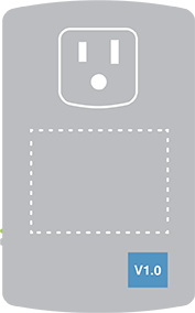
In-Wall Switches, Keypads & Outlets
1. If the product is already installed, remove the trim plate
2. Locate the sticker (on the aluminum bracket) which contains the letter "V" followed by a number like "1.0"


DIN Rail Modules
1. Locate the sticker on the left side of the module which contains the letter "V" followed by a number like "1.0"
2. If ganged together, you may need to remove the DIN Rail module from its mounting rail

Mini Remotes
1. Locate the sticker on the back of the remote which contains the letter "V" followed by a number like "1.0"

Wireless Sensors
1. On Open/Close sensors, remove the top housing. For Motion sensors, remove the back access panel and the battery.
2. Locate the sticker which contains the letter "V" followed by a number like "1.0"


Insteon Retail Device Numbers
Insteon products purchased through some third party retailers may refer to devices by a "Device Number." The Device Number does not affect an Insteon device's interoperability with Insteon products that have not been issued a device number.
| Device Number | Device Name |
|---|---|
| 10 | Dimmer Module |
| 11 | On/Off Module |
| 12 | Dimmer Switch |
| 14 | On/Off Switch |
| 15 | On/Off Outlet |
| 16 | Dimmer Switch (2-Wire) |
| 17 | Range Extender |
| 20 | Dimmer Keypad (6-Button) |
| 23 | LED Bulb |
| 24 | LED Bulb for Recessed Lights |
| 30 | Mini Remote (4-Scene Kit) |
| 32 | Motion Sensor |
| 33 | Leak Sensor |
| 36 | Smoke Bridge Kit |
| 40 | Open/Close Sensor |
| 41 | Hidden Door Sensor |
| 42 | Wired Thermostat |
| 43 | Garage Door Kit |
| 44 | IO Module |
| 45 | WiFi Camera (Black) |
| 46 | WiFi Camera (White) |
| 47 | Outdoor WiFi Camera |
| 50 | Ceiling Fan Controller |
| 51 | Dimmer Micro Module |
| 52 | On/Off Micro Module |
| 53 | Open/Close Micro Module |
| 55 | HD WiFi Camera (Black) |
| 56 | HD WiFi Camera (White) |
| 57 | Outdoor HD WiFi Camera |
X10 Programming for Insteon Devices
Accessing X10 Features within Select Insteon Devices
Back in 2005 when Insteon was first launched, it was the backwards compatibility that helped existing X10 users upgrade to something more reliable at their own pace. X10 is an antiquated technology and can be significantly impaired with noisy electrical environments. Whenever possible we recommend upgrading X10 hardware to Insteon for the best possible home control experience.
Please note that most new Insteon devices no longer support X10 communication.
Important: Except for setting or removing the primary address, all steps below require that you have an X10 controller that only sends House and Unit code (no On/Off command). Before attempting these steps you will need X10 hardware or software that supports the ability to send these commands (example: Maxi Controller #PHC02 or #SC503).
Setting the X10 Primary Address
- Press and hold the INSTEON device's Set button until it beeps. LED will blink
- Send the desired X10 Primary Address followed by ON 3 times (e.g. A1-AON A1-AON A1-AON). INSTEON device will exit linking mode and its LED will stop blinking
Removing the X10 Primary Address
- If you are no longer going to control your Insteon device with an X10 address, it is very important that you unlink it. Otherwise, your Insteon device will still respond to stray X10 commands and may cause your Insteon device to turn on at undesired times.
- Press and hold the Set button until it beeps. LED will blink
- Press and hold the Set button again until it beeps. LED will blink
- Send the X10 address to be removed followed by the ON command three times (e.g. B5-BON-B5-BON-B5-BON). Insteon device will exit unlinking mode and its LED will stop blinking
Setting the On-Level for the X10 Primary Address
Using an X10 controller, send:
O16 N16 M16 P16 M16
- Send the X10 primary address (house code and unit code)
- Use a linked controller to adjust your Insteon device's load to the desired brightness level. If you skip this step, the current on-level will be used. (If you turn the load off, the on level will become "resume" whereby the load will return to the brightness at which it was at just before being turned off)
Send the following X10 address sequence to lock in the new on-level:
P16 N16 M16 O16 M16
Setting the Ramp Rate for the X10 Primary Address
Using an X10 controller, send:
O16 N16 M16 P16 M16
- Send the X10 primary address (house code and unit code)
- Use an X10 controller to adjust your Insteon device's load to the brightness corresponding to the desired ramp rate using the table in the Insteon device's manual
Send the following X10 address sequence to lock in the new ramp rate:
O16 P16 N16 M16 O16
X10 Scene Address Programming
Most Insteon devices can be a member of up to 255 X10 scenes. An X10 scene address is simply a secondary X10 address. When an X10 ON command is sent to an X10 scene address, every X10 device with that X10 scene address will turn on to its independent On-Level at its independent Ramp Rate (if a dimmable device). Sending an X10 OFF command to an X10 scene address will turn off all devices that are members of that X10 scene, each at its independent Ramp Rate. Dimmable X10 devices will react to DIM and BRIGHT commands after the X10 scene address is sent. However, they will ignore ALL ON and ALL OFF commands for the X10 scene address.
Remotely Setting the On-Level for an X10 Scene Address
Using an X10 controller, send:
O16 N16 M16 P16 M16
- Use an X10 controller to adjust your Insteon device's load to the desired brightness level. If you skip this step, the current on-level will be used. A scene can trigger your Insteon device to go off by setting the on-level to 0%, or off
- Send the following X10 address sequence:
M16 N16 O16 P16
Send the desired X10 scene address (house code and unit code) to lock in the new on-level and X10 scene address
Setting the Ramp Rate for an X10 Scene Address
Using an X10 controller, send:
O16 N16 M16 P16 M16
- Send your Insteon devices X10 primary address (house code and unit code)
- Use an X10 controller to adjust your Insteon devices load to the brightness corresponding to the desired ramp rate using the table in the Insteon device's manual
Send the following X10 address sequence:
N16 O16 P16 M16 Scene Address
- Send the desired X10 scene address (house code and unit code) to lock in the new ramp rate and X10 scene address
Removing an X10 Scene Address
Using an X10 controller, send:
O16 N16 M16 P16 M16
- Send the your Insteon device's X10 primary address (house code and unit code)
- Send an X10 ON or OFF command
Send the following X10 address sequence:
O16 P16 M16 N16
- Send the X10 scene address you wish to remove (house code and unit code)