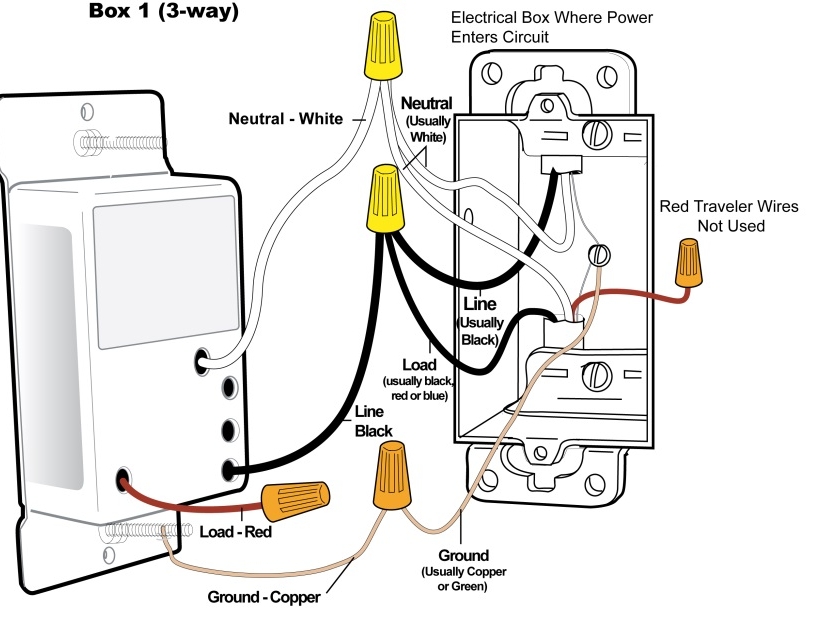
Change LED Brightness Levels (Keypads)

Adjust LED Brightness

Keypad LEDs can be set to any one of 32 brightness levels.
If KeypadLinc in 6-Button Configuration
 

  1. Simultaneously tap the A and D buttons

                            Keypad will beep
 

  1. Use the On and Off buttons to adjust the LED brightness
     
  2. When you have reached the desired brightness, simultaneously tap the A and D buttons again

                            Keypad will beep


If Keypad in 8-Button Configuration
 

  1. Simultaneously tap the C and F buttons

                            Keypad will beep
 

  1. Press and hold the On button to adjust the LED brightness. (The button will toggle between brightening and dimming.)
     
  2. When you have reached the desired brightness, simultaneously tap the C and F buttons

                             Keypad will beep

Change LED Brightness Levels (Switchlincs)

Change LED Backlight Brightness


Default = 50% bright.
 

Press and hold Set button until it beeps

            LED will start blinking
 

  1. Press and hold Set button until it beeps

            LED will continue blinking
 

  1. Press and hold Set button until it beeps

            LED will stop blinking
 

  1. Use SwitchLinc on and/or off buttons to brighten or dim LEDs to desired level
     
  2. Tap Set button

            SwitchLinc will double beep and return to ready mode

Installing Multi-way Circuits


Insteon Installation – Circuit with 3 (or more) Switches

Circuits with 3 or more switches are called 4-way (or 5-way, etc.) or multi-way. All switches in multi-way circuits need to be replaced by Insteon devices. Traditional switches also use traveler wires to get electricity from one switch to the next in a multi-way set-up. Since Insteon does not use traveler wires, you will need to turn those traveler wires into line wires so that you can provide power to the other Insteon switches. Then, link the switches together so that they all operate the same way. See the steps below for general instructions on how to do this.

Step 1: Turn off circuit breaker(s) and/or remove fuse(s) feeding wall boxes (verify that power is off)
Step 2: Pull all three switches from their wall boxes (4-way and higher switches have 3 or 4 wires).

***We recommend taking a picture of the wiring before you undo everything just in case.

Step 3: Remove wires from existing switches
Step 4: Make sure wires are safely separated from each other and turn power back on
Step 5: Using a voltage meter measure each wire to ground in all three boxes until you find the single wire supplying line voltage

  • We will now refer to that location as Box 1

  • The location having 2 sets of matching pairs of wires will be Box 2 (i.e. 2 reds and 2 blacks, or other matching colors). There are 2 travelers from Box 1 and 2 travelers leading to Box 3

  • The last box will have the load wire. That will be Box 3 


Step 6: Turn power back off

In Box 1

Step 1: Connect the switches bare copper wire to ground
Step 2: Connect the switches white wire to neutral
Step 3: Cap the switches red wire
Step 4: Connect the switches black wire to line plus one traveler (preferably black) and note color of the traveler you are using as this will carry line voltage to Box 2. This will supply the other Insteon switches with power.
Step 5: Cap any unused traveler wire.
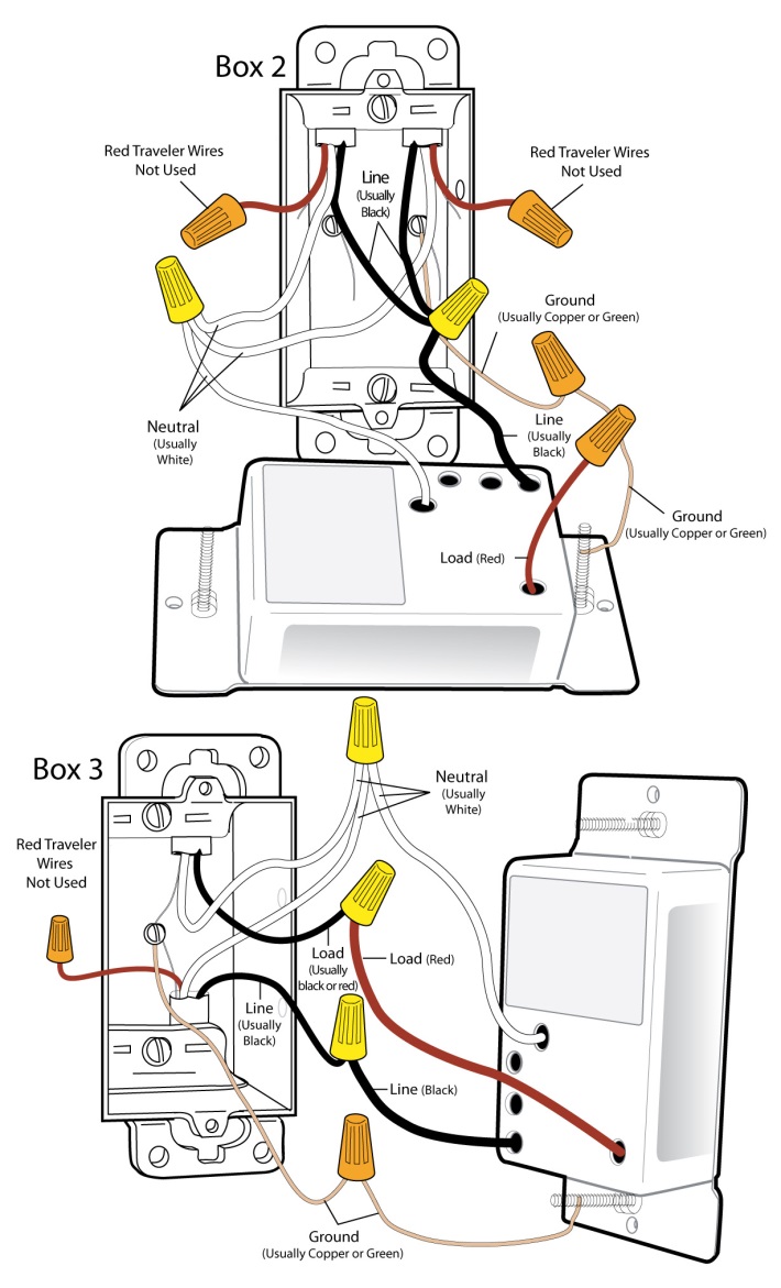
In Box 2

Step 1: Connect the switches bare copper wire to ground
Step 2: Connect the switches white wire to neutral
Step 3: Cap the switches red wire
Step 4: Connect the switches black wire to same color traveler from Box 1 that you connected to line along with same color traveler wires leading to Box 3.
Step 5: Cap the last unused traveler wire(s)

In Box 3 (Load)

Step 1: Connect the switches bare copper wire to ground
Step 2: Connect the switches white wire to neutral
Step 3: Connect the switches red wire to load
Step 4: Connect the switches black wire to line traveler from Box 2 (Line traveled from Box 1 through 2 into 3 usually black)
Step 5: Cap any unused traveler wire
Step 6: With the LEDs on the left, gently place the switches into the wall boxes and screw in place
Step 7: Turn power back on


  • The switches and connected load will turn on


Step 8: Add all the switches to a group. See “Groups”
Step 9: Verify all SwitchLincs are working properly by tapping each on and off


  • All the switches and the connected load will remain in sync


Step 10: Reinstall wall plates


Groups
 

(3-way linking)


Devices in a group remain synchronized. Every device in a group is both a controller of and a responder to all the other devices. The most common example of a group is a circuit with 2 switches (referred to as a 3-way circuit).

Example group for a ‘virtual’ 3-way circuit with switch “A” and switch “B”:


Step 1: Turn both A and B on
Step 2: Press and hold A’s Set button down until it beeps
 

  • A’s LED will start blinking


Step 3: Press and hold B’s Set button down until it double-beeps
 

  • A will double-beep and its LED will stop blinking (A is now a controller of B).


Step 4: With both switches still on press and hold B’s Set button until it beeps
 

  • B’s LED will start blinking


Step 5: Press and hold A’s Set button down until it double-beeps
 

  • B will double-beep and its LED will stop blinking (B is now a controller of A)


  • A and B are now grouped


Step 6: Test by turning load on and off from A and then B
 

  • The load(s) and both A and B LEDs will remain in synch


 (multi-way linking)


Example group for a ‘virtual’ 3-way circuit with switch “A,” switch “B,” and switch “C”:


Step 1: Turn A, B and C on
Step 2: Press and hold A’s Set button down until it beeps
 

  • A’s LED will start blinking


Step 3: Tap A’s set button one (1) time. It will beep one time.
 

  • A’s LED is start double-blinking


Step 4: Press and hold B’s Set button down until it double-beeps
 

  • A will double-beep and its LED will keep blinking (A is now a controller of B).


Step 5: Press and hold C’s set button down until it double-beeps.
 

  • A will double-beep and its LED will keep blinking (A is now a controller of C).


Step 6: Tap the set button on A to exit linking mode.
Step 7: Press and hold B’s Set button down until it beeps
 

  • B’s LED will start blinking


Step 8: Tap B’s set button one (1) time. It will beep one time.
 

  • B’s LED is start double-blinking


Step 8: Press and hold A’s Set button down until it double-beeps
 

  • B will double-beep and its LED will keep blinking (B is now a controller of A).


Step 9: Press and hold C’s set button down until it double-beeps.
 

  • B will double-beep and its LED will keep blinking (B is now a controller of C).


Step 10. Tap the set button on B to exit linking mode.
Step 11: Press and hold C’s Set button down until it beeps
 

  • C’s LED will start blinking


Step 12: Tap C’s set button one (1) time. It will beep one time.
 

  • C’s LED is start double-blinking


Step 13: Press and hold A’s Set button down until it double-beeps
 

  • C will double-beep and its LED will keep blinking (C is now a controller of A).


Step 14: Press and hold B’s set button down until it double-beeps.
 

  • C will double-beep and its LED will keep blinking (C is now a controller of B).


Step 15: Tap the set button on C to exit linking mode.


Verify operation by testing each switch to make sure that they all control and respond to each other.