
Assurance Kit - Guide de départ Rapide

Calibrate Temperature and Humidity on Insteon Wired and Wireless Thermsotats
If you believe that the temperature reading in your thermostat is incorrect, you can recalibrate the Thermostat by following these steps. It is strongly recommended that you use a known-good reference source for the calibrated temperature.
- Press and hold the Program button until the screen changes. This should take about five seconds.
- Tap the Time/Sensor button to enter temperature calibration mode.
- Tap the Mode button to switch between temperature and humidity calibration.
Temperature Calibration
- The top left number is the current temperature as read by the temperature sensor
- The larger number in the middle of the display is the calibrated temperature
- Tap the Up or Down buttons to adjust the displayed temperature to match the calibrated source.
- Press the Program button to exit calibration mode
Humidity Calibration
- The top left number is the current humidity level as read by the humidity sensor
- The lower left number is the calibrated humidity
- Press the Up or Down buttons to select the current humidity level
- Press the Program button to exit calibration mode
Identify your Insteon Hub Version
Sensor Shows Unknown Status

A sensor or other battery-powered device will show a yellow status circle and report "Unknown" if the Insteon Hub is unable to ascertain a sensor's status.
- If your sensor was recently added to the Insteon App, tap the sensor's set button. This should update the status in the Insteon Hub and the app should begin tracking the status of the sensor.
- If your sensor has been added to the Insteon App for a while and has only recently begun showing Unknown, it is possible that the Sensor's battery is low and needs to be replaced.
A wall-powered device may also show Unknown status. Ensure that the device is still connected to power and shows a red, green or white status LED. If not, check the power to the device. If power is normal, contact Insteon Support for additional troubleshooting or consult the product's Owner's Manual.
Control your Insteon Hub from your Android Wear Device using Tasker
If you would like to get more out of your Android Wear Watch, why not use it to control your Insteon home automation devices? By using the WearTasker App, it is now possible to run any Insteon task created on your Android smartphone (using the Tasker App) from an Android Wear watch. Using Tasker on your smartphone, build a list of the Insteon tasks you want to have available on your wrist. Once complete, simply tap the clock on your Android Wear watch, scroll down, and start WearTasker. Then, simply tap an Insteon task and it will execute on your smartphone. Enjoy convenient Insteon control - from your wrist!
Insteon is unable to offer support for the steps outlined in this article. Please consult this thread on the Insteon Support Forum to share your experiences with other Insteon customers.
Required Devices
A compatible Android smartphone (most devices running Android 4.4 or higher will work)
The Tasker Android App
An Android Wear-compatible device
The Wear Tasker Android App
An Insteon Hub (2012) or Insteon Hub (2014)
Getting Started
Before starting with Tasker and WearTasker, there are some pieces information you will need to get your devices setup with Insteon. Take a moment to gather the following information.
Insteon Hub User Name and Password. These credentials are different from your Insteon Connect account.
For Insteon Hub (2012), this information is located on the bottom of the device
For Insteon Hub (2014), this information can be found by navigating to Settings > House Settings > Hub User Name and Password
IP Address. Either your Hub's local IP address or if you wish for remote control when you are outside of your home's WiFi network, you will need to configure a DDNS setup.
Hub port number. The default port number is 25105. If this has been changed, you can find it by navigating to Settings > House > Port.
The to-be-controlled device(s) Insteon ID. See Locate your Device's Insteon ID for more information.
Understanding the URL String
Once you get a feel for the fundamentals, coding commands with the Tasker and WearTasker Apps will become easy. Commands are capable of turning devices on and off, brightening and dimming lights, or having lights dim to a preset brightness level. By taking the information collected above and combining it with Insteon Commands and Variables a command string can be created which will be sent to your hub as a post command.
Here is the URL String template
http://[User Name]:[Password]@[IP Address]:[Port]/3?0262[Insteon ID]0F[Command Type][Command Variable]=I=3
Here is a sample URL with information
http://danny:insteon@10.0.1.5:25105/3?02623256b80f11FF=I=3
| Component | Function |
|---|---|
| User Name | Insteon Hub User Name |
| Password | Insteon Hub Password |
| IP Address | Local or public IP address for the Insteon Hub. If a DDNS service has been configured, use the DDNS URL instead |
| Port | Insteon Hub port number. By default, the port is 25105 |
| 3?0262 | Indicates the beginning of a direct Insteon command. This does not change. |
| Insteon ID | Insteon ID for the controlled device. ID should be formatted without periods: aa00bb |
| 0F | This does not change |
| Insteon Command | Two digit command from table A1 |
| Command Variable | Two digit dimming variable from table A2 |
| =I=3 | Indicates the end of the command. This does not change. |
Device Command String Examples
This will turn on a device with ID 12.6E.8D to 75% brightness
http://admin:admin@10.0.1.5:25105/3?026212ce8d0f11bf=I=3
This command will slightly dim the same light
http://admin:admin@10.0.1.5:25105/3?026212ce8d0f1300=i=3
Scene Command String Examples
Command strings for scenes are created in a similar fashion; however, instead of using an Insteon ID, the command string will use a Scene ID. A Scene ID can be found within the Insteon for Hub App by going to Settings > Scenes, select the scene and identify the Group number. Scenes are limited to on and off commands only.
To turn group 1 on, the command would be
http://admin:admin@10.0.1.5:25105/0?111=I=0
To turn group 1 off, the command would be
http://admin:admin@10.0.1.5:25105/0?131=I=0
Adding Commands into Tasker
Open Tasker and navigate to Tasks
Tap the + button to create a new task and give it a name
After the Edit screen appears, tap the + button again and select Net > HTTP Post and enter your command in the server:port field
Go back and tap the Play button to test your command
Adding Control to your Android Wear Device
Create a new Task by tapping the + button on the task screen and give it a name
On the Edit Task screen, tap + and select Plugin > Wear Tasker
Tap the Edit button to configure the task
Configure a Location Profile for quick access to lighting commands
Every time your phone connects to a specified WiFi network, your watch will display the desired controls.
Go to Profiles and tap the + button
Select State > Net > WiFi Connected and then browse for your home's WiFi Network SSID
Tap Back and select a Task
Select the Task you created for Wear Tasker
General Insteon Control
| Insteon Command | Function |
|---|---|
| 11 | On - Can Be used with Variable to set default brightness level |
| 12 | Fast On - Will go immediately to full brightness - No ramp rate |
| 13 | Off - Can Be used with Variable to set default brightness level |
| 14 | Fast Off - Will go immediately off - No ramp rate |
| 15 | Brighten - Incrementally increase brightness of a dimmable device |
| 16 | Dim - Incrementally decrease brightness of a dimmable device |
Brightness
| Insteon Command | Function |
|---|---|
| 0 | 0% |
| 19 | 10% |
| 40 | 25% |
| 7F | 50% |
| BF | 75% |
| E6 | 90% |
| FF | 100% |
Thermostat Control
For the heat and cool set point command strings, ** denotes the desired set point. This command example will switch a Thermostat to Heat:
http://admin:admin@10.0.1.5:25105/3?02623093181F6B040000000000000000000000000091=I=3
| Insteon Command | Function |
|---|---|
| 1F6B040000000000000000000000000091 | Heat On |
| 1F6B050000000000000000000000000090 | Cool On |
| 1F6B06000000000000000000000000008F | Auto On |
| 1F6B07000000000000000000000000008E | Fan On |
| 1F6B08000000000000000000000000008D | Fan Off |
| 1F6B09000000000000000000000000008C | All Off |
| 1F6C6400000000000000000000000000** | Cool Set Point |
| 1F6D6400000000000000000000000000** | Heat Set Point |
Useful Resources
Automatically Generate Insteon Hub HTTP Commands - https://www.smarthome.com.au/smarthome-blog/insteon-hub-http-commands/
Probably the most useful resource for generating Insteon Direct Commands, this will allow you to generate the commands automatically for the most useful functions, such as setting brightness levels or changing your thermostat’s temperature.
Rich Stevenson’s Blog - https://www.richstevenson.com/category/insteon-home-automation/
An excellent rundown and explanation as to just how these direct commands work
Locate your device's Insteon ID
All Insteon devices except for WiFi Cameras have an Insteon ID. Use this article to help locate the Insteon ID for your product.
The Insteon ID is usually printed on a small, white rectangular sticker affixed in the locations described below. All Insteon IDs take the form of three hexadecimal pairs (A1.B2.C3).
| Device | Insteon ID Location |
|---|---|
| Dimmer Module | On the back |
| On/Off Module | |
| Outdoor On/Off Module | |
| LED Bulb | On the top of the bulb lens |
| LED Bulb for Recessed Lights | |
| Dimmer Switch | On the metal mounting bracket in one of the four corners |
| Dimmer Switch (1000W) | |
| Dimmer Switch (2-Wire) | |
| On/Off Switch | |
| Dimmer Keypad (6-Button) | |
| Dimmer Keypad (8-Button) | |
| On/Off Keypad (6-Button) | |
| On/Off Keypad (8-Button) | |
| Dimmer Outlet | |
| On/Off Outlet (2007) | |
| On/Off Outlet (2014) | |
| Wired Thermostat | On the inside of the cover as well as near the screw terminals |
| Wireless Thermostat | |
| Thermostat Adapter | On the back |
| Mini Remote (Wireless Switch) | On the back, towards the bottom |
| Mini Remote (4-Scene) | |
| Mini Remote (8-Scene) | |
| WiFi Camera | This device does not have an Insteon ID |
| HD WiFi Camera | |
| Outdoor WiFi camera | |
| HD Outdoor WiFi Camera | |
| Open/Close Sensor | On the circuit board beneath the enclosure cover |
| Hidden Door Sensor | On the circuit board beneath the battery |
| Motion Sensor | On the back, above the battery cover |
| Leak Sensor | On the bottom |
| Smoke Bridge | On the back |
| IO Module | On the back |
| Ceiling Fan Controller | On the bottom |
| Dimmer Micro Module | On the back |
| On/Off Micro Module | |
| Open/Close Micro Module | |
| Ballast Dimmer | On the top |
| Dimmer In-Line Module | On the back |
| On/Off In-Line Module | |
| 220V Load Controller | On the front |
| Dimmer DIN Rail Module | On the back |
| On/Off DIN Rail Module | |
| MorningLinc | On the back |
| IRLinc Transmitter | |
| IRLinc Receiver | |
| SeriaLinc | |
| Range Extender | On the back |
| Energy Display | On the back |
| iMeter Solo | On the back |
| SynchroLinc |
Using the Insteon Motion Sensor with the Insteon Hub
When you add the Motion Sensor (2842-222) to the Insteon for Hub application, your motion sensor will have extra settings for you to use. These options can be changed at any time by navigating to the Device's settings.
Tap on the motion sensor. These extra settings can be found by tapping "Device Options." After you expand the options you will see the following:
- Motion LED – This option turns off the red PIR light that flashes in the front of the motion sensor when it detects motion. (It will still operate during setup)
- Night Only – Tells the motion sensor that you want it to work only at night.
- Motion Countdown – The amount of time that a motion sensor will wait before telling linked devices to turn off.
- Light Sensitivity – How sensitive the motion sensor is to detecting light. The lower the number, the less light is needed for the motion sensor to detect daytime while the higher the setting, more light is needed for the motion sensor to read daytime.
- Occupancy Mode – During normal operation, once the countdown is triggered from the motion sensor, the motion sensor will ignore all other motions until the countdown reaches zero, and then the connected devices are turned off. With “Occupancy Mode” enabled, when the motion sensor detects motion, it will restart the countdown timer over and over again until movement is no longer detected.
- On Only Mode – This mode causes the motion sensor to only send the “ON” command and ignore the countdown. The customer will be responsible for turning off the light when they leave the room.
Supported Insteon Devices with the Insteon for Hub App
This chart shows supported Insteon devices on iOS, Android, Windows and Windows Phone. The information in this chart is applicable for Insteon Hub (2242-222) and Insteon Hub (2245-222) with the Insteon for Hub app.
For a list of supported devices for the HomeKit-enabled Insteon Hub (2243-222) and Insteon+ app, see this article instead.
If you need help identifying your version of Insteon Hub, see this article.
| iOS | Android | Windows | Windows Phone | |
| Dimmer Module | ||||
| On/Off Module | ||||
| Outdoor On/Off Module | ||||
| LED Bulb | ||||
| LED Bulb for Recessed Lights | ||||
| Dimmer Switch | ||||
| Dimmer Switch (1000W) | ||||
| Dimmer Switch (2-Wire) | ||||
| On/Off Switch | ||||
| Dimmer Keypad (6-Button) | Load Only | Load Only | ||
| Dimmer Keypad (8-Button) | Load Only | Load Only | ||
| On/Off Keypad (6-Button) | Load Only | Load Only | ||
| On/Off Keypad (8-Button) | Load Only | Load Only | ||
| Dimmer Outlet | ||||
| On/Off Outlet (2007) | ||||
| On/Off Outlet (2014) | Upper Outlet Only | Upper Outlet Only | ||
| Wired Thermostat | ||||
| Wireless Thermostat | - | - | - | - |
| Thermostat Adapter | ||||
| Mini Remote (Wireless Switch) | - | - | - | |
| Mini Remote (4-Scene) | - | - | - | |
| Mini Remote (8-Scene) | - | - | - | |
| WiFi Camera | ||||
| HD WiFi Camera | - | - | ||
| Outdoor WiFi camera | ||||
| HD Outdoor WiFi Camera | - | - | ||
| Open/Close Sensor | ||||
| Hidden Door Sensor | ||||
| Motion Sensor | ||||
| Leak Sensor | ||||
| Smoke Bridge | ||||
| IO Module | ||||
| Ceiling Fan Controller | Light Only | Light Only | ||
| Dimmer Micro Module | ||||
| On/Off Micro Module | ||||
| Open/Close Micro Module | ||||
| Ballast Dimmer | ||||
| Dimmer In-Line Module | ||||
| On/Off In-Line Module | ||||
| 220V Load Controller | ||||
| Dimmer DIN Rail Module | ||||
| On/Off DIN Rail Module | ||||
| MorningLinc / MiLock Controller | - | - | ||
| IRLinc Transmitter | - | - | - | - |
| IRLinc Receiver | - | - | - | - |
| SeriaLinc | - | - | - | - |
| Range Extender | ||||
| Energy Display | - | - | - | - |
| iMeter Solo | - | - | - | - |
| SynchroLinc | - | - | - | - |
| X10 | Hub (2012) Only | Hub (2012) Only | - | - |
Keypad Button Change Kit (Clear)

Locate your device's Set Button
Use this article to help locate the set button on your Insteon Device.
| Device | Set Button Location |
|---|---|
| Hub (2012) | On the back panel, next to the power connector. On Insteon Hub (2012), only use the set button when instructed to do so. |
| Hub (2014) | On the back panel, next to the ethernet connector. On Insteon Hub (2014), only use the set button when instructed to do so. |
| Hub Pro | On the back panel, next to the power connector. |
| Dimmer Module | On the right-hand side, beneath the bright and dim buttons |
| On/Off Module | On the right-hand side, beneath the on and off buttons |
| Outdoor On/Off Module | On the bottom, to the right of the controlled power outlet |
| LED Bulb | LED Bulb does not have a set button. To "press" the set button, follow the following steps:
|
| LED Bulb for Recessed Lights | LED Bulb for Recessed Lights does not have a set button. To "press" the set button, follow the following steps:
|
| Mini Remote (Wireless Switch) | On the bottom, between the Micro USB connector and On/Off Switch |
| Mini Remote (4-Scene) | On the bottom, between the Micro USB connector and On/Off Switch |
| Mini Remote (8-Scene) | On the bottom, between the Micro USB connector and On/Off Switch |
| Dimmer Switch | Beneath the paddle, in-line with the switch trim |
| Dimmer Switch (1000W) | Beneath the paddle, in-line with the switch trim |
| Dimmer Switch (2-Wire) | Beneath the paddle, in-line with the switch trim |
| On/Off Switch | Beneath the paddle, in-line with the switch trim |
| Dimmer Toggle Switch | Beneath the toggle switch |
| On/Off Toggle Switch | Beneath the toggle switch |
| Dimmer Keypad (6-Button) | Beneath the Off button, in-line with the keypad trim |
| Dimmer Keypad (8-Button) | Beneath the G and H buttons, in-line with the keypad trim |
| On/Off Keypad (6-Button) | Beneath the Off button, in-line with the keypad trim |
| On/Off Keypad (8-Button) | Beneath the G and H buttons, in-line with the keypad trim |
| Dimmer Outlet | Between the upper and lower outlets |
| On/Off Outlet (2011) | Between the upper and lower outlets |
| On/Off Outlet (2014) | Between the upper and lower outlets. Each set button controls the outlet to which it is nearest. |
| Wired Thermostat | Beneath the cover, in the lower left-hand corner (later versions have the set button exposed through the cover) |
| Wireless Thermostat | Beneath the cover, in the lower left-hand corner |
| Venstar Thermostat Adapter | On the right side, next to the status LED |
| Open/Close Sensor | For models manufactured in 2012 or later, on the top, to the right of the status LED. For models manufactured prior to 2012, beneath the cover between the external sensor terminals and the jumper pins. |
| Hidden Door Sensor | On the top, towards the rear of the sensor in a recessed cove |
| Motion Sensor | Beneath the rear cover, to the right of the jumper pins and sensitivity dials |
| Leak Sensor | On the top, to the right of the status LED and antenna |
| Smoke Bridge | On the right-hand side |
| IO Module | On the right-hand side, next to the status LED |
| Ceiling Fan Controller | On the end nearest the wires, labeled Fan and Light |
| Dimmer DIN Rail Module | On the front, beneath the paddle |
| On/Off DIN Rail Module | On the front, beneath the paddle |
| Dimmer Micro Module | In the upper left corner, beneath the Bright and Dim buttons |
| On/Off Micro Module | In the upper left corner, beneath the On and Off buttons |
| Open/Close Micro Module | In the upper left corner, beneath the Open and Close buttons |
| 0-10V Ballast Dimmer | On the right side, next to the status LED |
| Dimmer In-Line Module | On the front, beneath the Off button |
| On/Off In-Line Module | On the front, in the lower left corner |
| 220V Load Controller (Normally Open) | On the front, to the left of center |
| 220V Load Controller (Normally Closed) | On the front, to the left of center |
| Door Lock and Deadbolt Controller | On the right-hand side, next to the status LED |
| IR Transmitter | On the right-hand side, next to the status LED |
| IR Receiever | On the right-hand side, next to the status LED |
| Serial Bridge | On the right-hand side, next to the status LED |
| iMeter Solo | On the right-hand side, next to the status LED |
| SynchroLinc | On the right-hand side, next to the status LED |
| Range Extender | On the right-hand side |
Insteon Hub (2012) and Daylight Saving Time
Insteon has identified an issue that may prevent Insteon Hub (2012) from automatically adjusting to Daylight Saving Time on 8 March 2015.
To reset your Hub's internal clock, perform the following actions:
- Log into your Insteon App
- Navigate to Settings
- Select House
- Select Hub Location and follow the steps to set your Hub's physical location. If you have already performed this step prior, you may need to perform it again to update your Hub's internal clock.
If you do not perform these steps, your Hub should automatically adjust it's internal clock to match Daylight Saving Time but it will do so 24 hours after the official transition.
This issue does not affect Insteon Hub (2014).
2-Wire (AT&T/SBC) Router - Port Forwarding Guide
Note: 2-Wire routers are usually distributed by ATT/SBC in North America
Step 1: Open your web browser and enter router’s IP address (192.168.1.254 by default) in the address bar. Enter username and then password to login.

Step 2: Find and click on the Firewall tab on the top right.
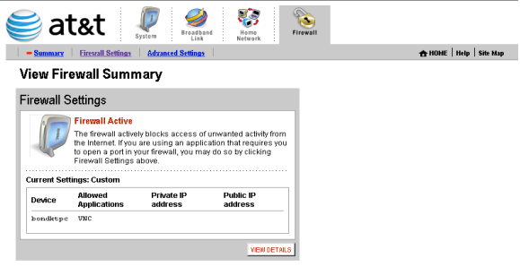
Step 3: Find and click on the Firewall tab on the top right. Once the page is loaded, click on Add a new user-defined application.

Step 4: For ‘Application Name’ give this entry a name e.g. INSTEON Camera
For ‘Protocol’ Choose ‘TCP’
For ‘Port (or Range)’ in ‘From’ & ‘To’ enter the ports to be forwarded.
Example: 8090 to 8090
For ‘Protocol Timeout (seconds)’ & ‘Map to Host Port’ & ‘Application Type’ you can leave these all at their default values.
Click ‘Add Definition’
Repeat this step for all ports.
Once you have entered all the ports for this entry click ‘Back’

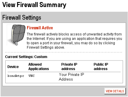
Step 5: For ‘Select a computer’ choose the INSTEON Camera’sIP address to forward the ports to.
Choose ‘Allow individual applications’
Choose ‘User-defined’ from the drop down box
In the list on the left choose the entry you created “INSTEON Camera” and then click ‘Add’
Repeat this step for each entry you need to add.
Once you are all done click ‘Done’

Step 6: Once you’ve done that, INSTEON Camera should appear in the Hosted Applications
Click the Done button at the bottom right corner of the screen, and you should see the following screen:
Step 7: To view the camera over the internet enter you router external IP address which can be found by typing www.whatismyipaddress.com into your browser.
Enter your IP address (eg. 24.76.212.746): port for the camera (e.g. port 8090).
24.76.212.746:8090 is what should be typed into you browser.
You can check port is forwarded successful or not on
http://www.yougetsignal.com/tools/open-ports/

Verizon/Actiontec Router/Modem - Port Forwarding Guide
Actiontec GT704WG & GT704WGB gateways
Step 1: Open your web browser and enter router’s IP address (192.168.0.1 by default) in the address bar. Enter username (“admin” by default) and then password (“password” by default).

Step 2: Navigate to Security > Applications. Select the camera on your network where you want to use port forwarding in the PC Name field. Select User in the Category list and click New.

Step 3: Enter a name for your port forwarding rule in the Rule Name field.
Select TCP in protocol and enter camera’s port number in port start, port end and port map start. Click Apply to save your rule settings.
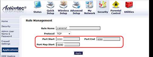
Click Back to return to the Applications screen.
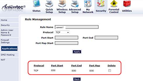
Step 4: Select the name of the rule you just created in the Available Rules box and click Add to use this port forwarding rule on camera. Click Apply.

You can check port is forwarded successful or not on
http://www.yougetsignal.com/tools/open-ports/

Thomson TG585 - Router/Modem Port Forwarding Guide
Note: This router/modem forwards based on computer name and not IP address. So there is no need to set a static IP.
Step 1: Open your web browser and enter router’s IP address (192.168.0.1 by default) in the address bar. Enter username ("admin" by default) and then password (blank by default)

Step 2: Navigate to Toolbox > Game & ApplicationSharing. Once the page is done loading click on "Create a new game or application".
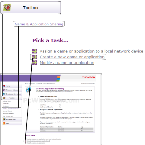
Step 3: For Name, give the new rule a name.
Choose "Manual Entry of Port Maps and then click "Next".

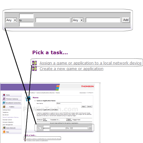
Step 4: For 'Protocol' Choose 'TCP'. For 'Port Range' enter camera’s port. Example: 2100 to 2100. Click 'Add'.
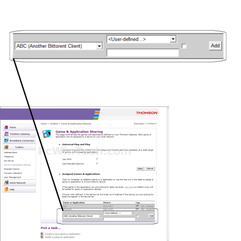
Step 5: In the "Game or Application" list, choose the name of the new rule you created.
For "Device" you can either choose the computer name to forward to, or choose "User-Defined" to manually enter a IP address.
If you choose "User-Defined" a new text box will show up, enter the local IP to forward to here.
Once you are all done click 'Add'.
If camera is "User-Defined", set a static IP address for camera first.
You can check port is forwarded successful or not on
http://www.yougetsignal.com/tools/open-ports

Netgear Router - Port Forwarding Guide
Step 1: Open your web browser and enter router’s IP address (192.168.0.1 by default) in the address bar. Enter username ("admin" by default) and then password (blank by default)

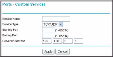
Step 2: Navigate to Port Forwarding/Port Triggering and select Port Forwarding. Select HTTP from the Service Name drop-down list. Click Add Service button.

In the Service Name, type a name, like “camera”
In the Service Type, select TCP/UDP.
In the Starting Port, enter camera’s port number. Eg:8090
In the Ending Port, enter camera’s port number. Eg:8090
In the Server IP Address, enter camera’s IP address. Eg:192.168.1.5
Click Apply. You may need to restart the router for the changes to take effect.
You can check port is forwarded successful or not on
http://www.yougetsignal.com/tools/open-ports/

Linksys/Cisco Router - Port Forwarding Guide
Step 1: Open your web browser and enter router’s IP address (192.168.0.1 by default) in the address bar. Enter username ("admin" by default) and then password (blank by default)

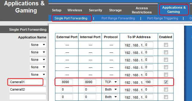
Step 2: Click Applications & Gaming > Single Port Forwarding tab.
You enter a name what you like for the port forwarding. (Eg: Camera01)
Enter camera’s port number in External Port and Internal Port, select TCP for Protocol. (Eg: 8090)
Enter camera’s IP address and check Enable box. (Eg: 192.168.1.190)
After completing all the necessary entries, go to the bottom and click Save Settings.
You can check port is forwarded successful or not on
http://www.yougetsignal.com/tools/open-ports/

D-Link Router - Port Forwarding Guide
Step 1: Open your web browser and enter router’s IP address (192.168.0.1 by default) in the address bar. Enter username ("admin" by default) and then password (blank by default).

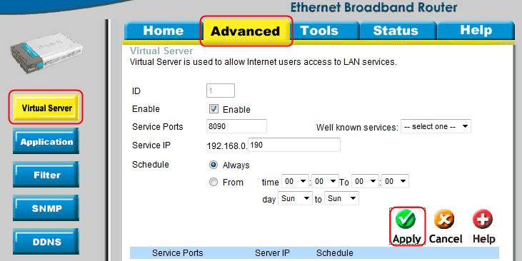
Step 2: Navigate to Advanced > Virtual Server
Enter the following information:
Check the box next to Enable.
Enter camera’s port in Service Ports. (Eg: 8090)
Enter camera’s IP address in Service IP. (Eg: 192.168.0.190)
Click Always in schedule.
Click Apply and then click Restart to save your changes.
You can check port is forwarded successful or not on
http://www.yougetsignal.com/tools/open-ports/

Belkin Router - Port Forwarding Guide
Step 1: Open your web browser and enter router’s IP address (192.168.0.1 by default) in the address bar. Enter username your router password (the default password is blank).

Step 2: Navigate to Firewall > Virtual Servers

Step 3: Check Enable
In the Description column enter a description of your network device (e.g. INSTEON Camera 1)
In “Inbound port” enter camera’s port number.
Next choose the “Type” you want to use. (For INSTEON cameras we will use TCP or Both)
Enter the Camera’s IP address in “Private IP Address”
In “Private port” enter camera’s port number.
Repeat step 5 for any more ports you want to forward.
Click on “Apply Changes”
You can check port is forwarded successful or not on
http://www.yougetsignal.com/tools/open-ports/

Port Forwarding Guides
The port forwarding set up is reliant upon the specific brand and model number of the router being used. The Insteon Hub (2012) and Insteon WiFi Cameras require forwarding for access to your network device from outside of your home network. The new Insteon Hub (2014) does not require port forwarding. Regardless of the router being used, the process of port forwarding is similar. Below is a list of port forwarding guides for popular routers:
Please follow the link below if your router is not listed.