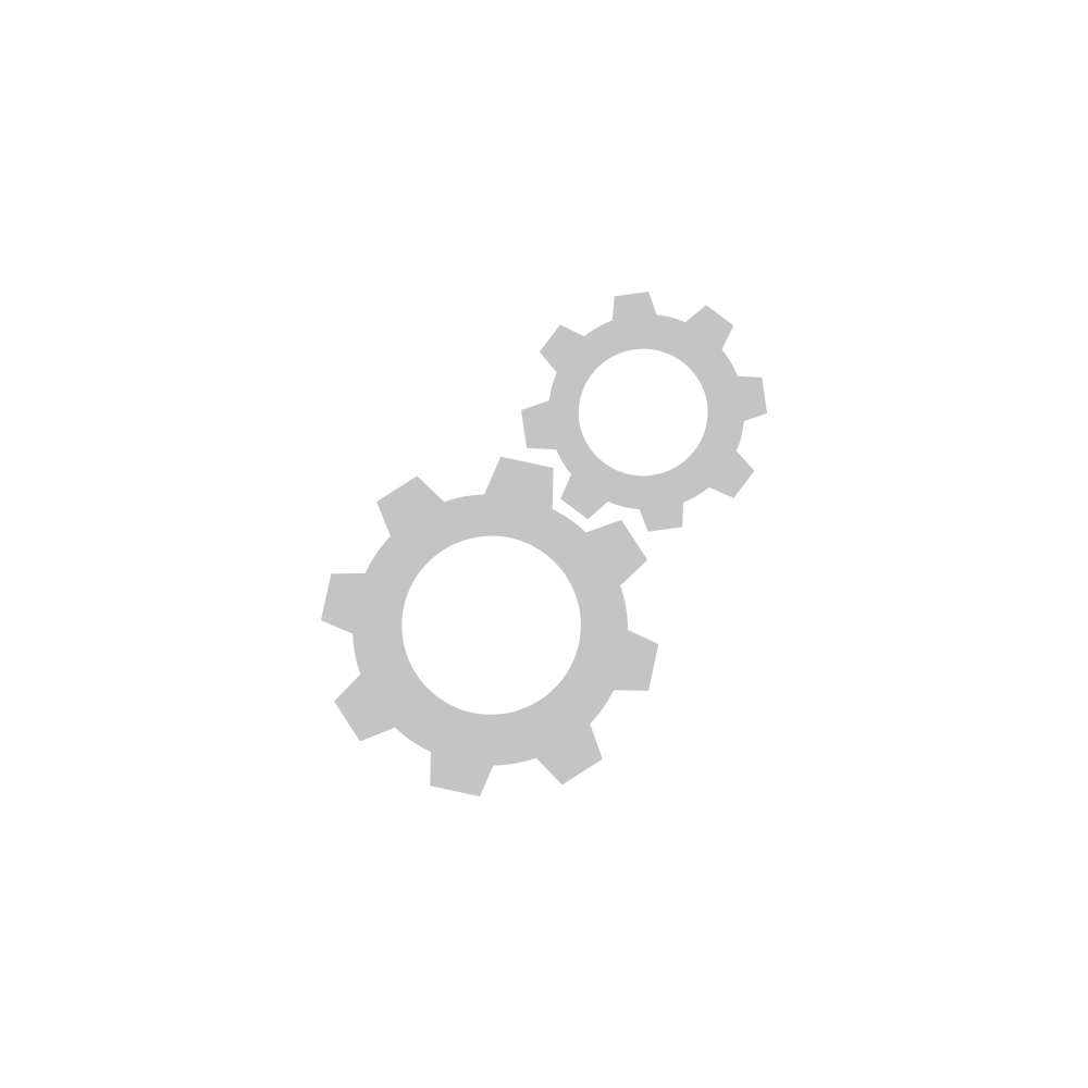
Dimmer DIN Rail Module Setup

Guides and Manuals

Quick Start Guide

Owner's Manual


Going Further


Ceiling Fan Controller Setup

Guides and Manuals

Quick Start Guide

Owner's Manual


Going Further


Open/Close Micro Module Setup

Getting Started

step-1.png
Turn off power at the service panel and remove the existing wall switch.
step-2.png

Unfold all of the wires from within the junction box. Separate the black wires and cap them with wire nuts.

step-3.png
Turn on power and use a voltage detector to identify the live wire; this is your line wire.
 
step-4.png
Turn off power and connect the corresponding wires.
step-5.png
Reinstall your wall switch, attach the wall plate and turn on power.
step-6.png

Follow the on-screen instructions in the INsteon app to add Micro Module.


Guides and Manuals

Quick Start Guide

Owner's Manual


Going Further


On/Off Micro Module Setup

Getting Started

step-1.png
Turn off power at the service panel and remove the existing wall switch.
step-2.png

Unfold all of the wires from within the junction box. Separate the black wires and cap them with wires nuts.

step-3.png
Turn on power and use a voltage detector to identify the live wire; this is your line wire.
 
step-4.png
Turn off power and connect the corresponding wires.
step-5.png
Reinstall your wall switch, attach the wall plate and turn on power.
step-6.png

Follow the on-screen instructions in the Insteon app to add Micro Module.


Guides and Manuals

Quick Start Guide

Owner's Manual


Going Further


Dimmer Micro Module Setup

Getting Started

step-1.png
Turn off power at the service panel and remove the existing wall switch.
step-2.png

Unfold all of the wires from within the junction box. Separate the black wires and cap them with wire nuts.

step-3.png
Turn on power and use a voltage detector to identify the live wire; this is your line wire.
 
step-4.png
Turn off power and connect the corresponding wires.
step-5.png
Reinstall your wall switch, attach the wall plate and turn on power.
step-6.png

Follow the on-screen instructions in the Insteon app to add Micro Module.


Guides and Manuals

Quick Start Guide

Owner's Manual


Going Further


Mini Remote (4-Scene) Setup

Guides and Manuals

Quick Start Guides

Owner's Manuals


Going Further


Mini Remote (Wireless Switch) Setup

Guides and Manuals

Quick Start Guide

Owner's Manual


Going Further


Wireless Thermostat Setup

Guides and Manuals

Quick Start Guide

Owner's Manual


Going Further

Wired Thermostat for Heat Pumps Setup

Getting Started

steps-0.png

Before installing Insteon Thermostat for Heat Pumps, ensure your system is compatible.

Learn More →

step-1.png
Turn off power and remove your old thermostat's cover.
step-3.png

Take a picture of your thermostat's wires and apply the optional wire labels. Carefully remove the old mounting bracket.

 
step-4.png
Install Insteon Thermostat for Heat Pumps and connect the wires. Close the cover and turn on power.

Wire colors may vary. Not all wires may be used. Match your wires to the labels printed on Insteon Thermostat for Heat Pumps.

step-5.png

Follow the on-screen instructions in the Insteon app to add Insteon Thermostat for Heat Pumps.

step-5.png

When prompted, press and hold the set button until Thermostat double-beeps.


Guides and Manuals

Quick Start Guide

Owner's Manual


Going Further


Wired Thermostat Setup

Guides and Manuals

Quick Start Guide

Owner's Manual


Going Further

I/O Module Setup

Guides and Manuals

Quick Start Guide

Owner's Manual


Going Further


Smoke Bridge Setup

Guides and Manuals

Quick Start Guide

Owner's Manual


Going Further


Water Leak Sensor Setup

Guides and Manuals


Going Further


Hidden Door Sensor Setup

Guides and Manuals

Quick Start Guide

Owner's Manual


Going Further


Open/Close Sensor Setup

Guides and Manuals

Quick Start Guide

Owner's Manual


Going Further


On/Off Keypad Setup

The content of this article applies to both Insteon On/Off Keypad (8-Button) and Insteon On/Off Keypad (8-Button).

Getting Started

step-1.png
Turn off power at the service panel and remove the existing wall switch.
step-2.png

Unfold all of the wires from the junction box. Separate the black wires and cap them with wire nuts.

If your switch's wires do not match the diagram, consult the additional wiring diagrams available below.

step-3.png
Turn on power and use a voltage detector to identify the live wire; this is your line wire.
 
step-4.png
Turn off power and connect the corresponding wires from the junction box with the Insteon Wall keypad and cap them with wire nuts.
step-5.png
Install Insteon Wall Keypad, attach the wall plate and turn on power.
step-6.png

Follow the on-screen instructions in the Insteon app to add On/Off Keypad.


Guides and Manuals

Quick Start Guides

Owner's Manuals


Going Further

Dimmer Keypad Setup

The content of this document applies to both Insteon Dimmer Keypad (6-Button) and Insteon Dimmer Keypad (8-Button).

Getting Started

step-1.png
Turn off power at the service panel and remove the existing wall switch.
step-2.png

Unfold all of the wires from the junction box. Separate the black wires and cap them with wire nuts.

If your switch's wires do not match the diagram, consult the additional wiring diagrams available below.

step-3.png
Turn on power and use a voltage detector to identify the live wire; this is your line wire.
 
step-4.png
Turn off power and connect the corresponding wires from the junction box with the Insteon Wall Keypad and cap them with wire nuts.
step-5.png
Install Insteon Wall Keypad, attach the wall plate and turn on power.
step-6.png

Follow the on-screen instructions in the Insteon app to add Dimmer Keypad.


Bulb Compatability

 
bulb-types.png

Only use dimmable bulbs with Insteon Dimmer Keypad


Guides and Manuals

Quick Start Guides

Owner's Manuals

On/Off Toggle Switch Setup

Guides and Manuals

Quick Start Guide

Owner's Manual


Going Further

Dimmer Toggle Switch Setup

Guides and Manuals

Quick Start Guide

Owner's Manual


Going Further

On/Off Switch Setup

Getting Started

step-1.png
Turn off power at the service panel and remove the existing wall switch.
step-2.png

Unfold all of the wires from the junction box. Separate the black wires and cap them with wire nuts.

If your switch's wires do not match the diagram, consult the additional wiring diagrams available below.

step-3.png
Turn on power and use a voltage detector to identify the live wire; this is your line wire.
 
step-4.png
Turn off power and connect the corresponding wires from the junction box with the Insteon Wall Switch and cap them with wire nuts.
step-5.png
Install Insteon Wall Switch, attach the wall plate and turn on power.
step-6.png

Follow the on-screen instructions in the Insteon app to add On/Off Switch.


Guides and Manuals

Quick Start Guides

Owner's Manual